Serveur d'automatisation Kisters (KAS)
Outil de traitement par lots pour la conversion automatisée sans intervention de l'utilisateur
Le Kisters Automation Server KAS est le complément idéal pour tous les composants de la famille de produits 3DViewStation lorsqu'il s'agit d'automatiser des procédures répétitives. Il s'agit principalement de la conversion de données CAD 3D natives en format de données 3DVS léger. Par exemple, une carte Catia de 5 Go, qui prend 5 minutes à charger en mode de chargement natif, peut être chargée en seulement 1 seconde après la conversion au format 3DVS. Toutes les informations peuvent être conservées ou réduites selon les paramètres. La conversion peut être monolithique ou entièrement éclatée, c'est-à-dire dans un fichier 3DVS par fichier de géométrie. Cela réduit considérablement l'effort de conversion après la modification d'une pièce individuelle intégrée éventuellement plusieurs fois. Le KAS peut également être utilisé pour générer automatiquement des vignettes pour les systèmes PLM. Ou pour exporter toutes les vues qui ont été créées pour un assemblage dans un format 3D ou 2D ou pour exporter l’assemblage entier dans un format 3D standard.
Parlez-nous maintenant – nous serons heureux de vous conseiller
Nous sommes heureux de vous conseiller
Ventes
+49 2408 9385 517
Les exemples de projets suivants proviennent de nos clients utilisant l’outil de traitement par lots KAS :
Un fabricant d'hélicoptères convertit toutes ses données CAD natives au format 3DVS avant de les visualiser. La visualisation de l'hélicoptère configuré est ainsi extrêmement accélérée. En tant que monolithe, le temps de chargement est maintenant inférieur à 10 secondes pour 2 à 3 millions de pièces. Le système de CAO n'a jamais été capable même approximativement de charger l'hélicoptère complet.
Un constructeur de camions utilise le KAS pour convertir ses données CAO natives par batch au format léger 3DVS. Certains fichiers sont contrôlés par des métadonnées, et sont en plus également transformés dans BREP. Une fois le camion configuré, il est selon les souhaits du client converti en données STEP partiellement transformées via le KAS, des dessins en 2D sont générés automatiquement.
Une société d'ingénierie d'usine utilise la KAS pour réduire ses quelque 5 TB ( !) Convertir des données CAO au format 3DVS. Il est ainsi capable de charger les données d'une usine d'environ 200 millions de composants avec le 3DViewStation WebViewer.
Un chantier naval utilise KAS pour convertir un navire complet au format 3DVS. Le temps de chargement ultérieur des quelque 10 millions de composants est d'environ 15 secondes pour l'édition VR, mais aussi pour la version de bureau et la version WebViewer.
Notre solution de collaboration : VisShare utilise KAS en arrière-plan pour convertir les données natives au format 3DVS et pour générer les images de prévisualisation.
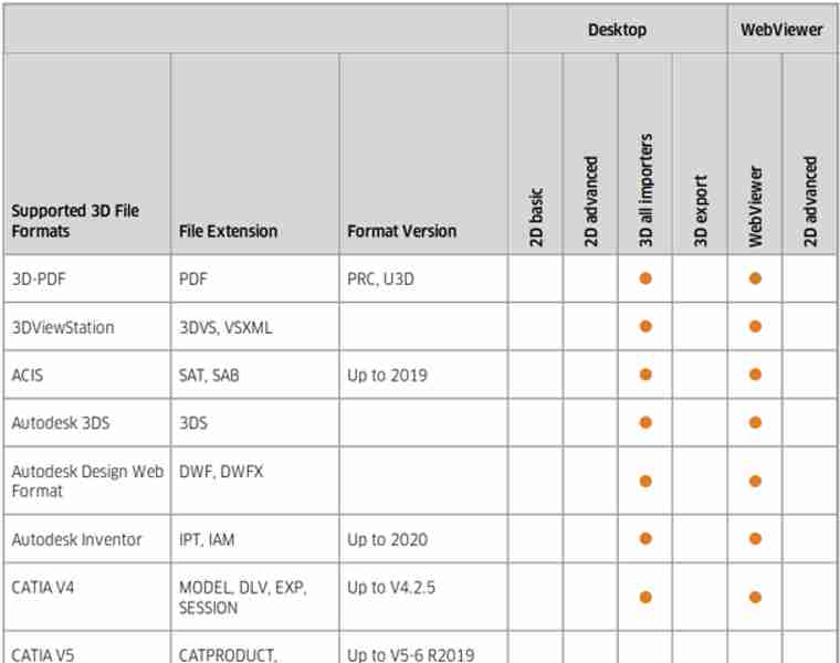
Formats de données 2D supportés
Extrait :
Importation 2D de dessins, d'Office, d'images :
Catia CatDrawing, NX 2D, Creo DRW, Solidworks slddrw, DWG, DXF, HPGL, 2D PDF, TIFF, JPEG...
Exportation 2D :
DXF, PDF, CGM, PNG, SVG, BMP...
Le logiciel interactif Kisters 3DViewStation ainsi que l'outil de traitement par lots KAS ne sont pas des convertisseurs classiques, mais facilitent la conversion de formats de fichiers 3D vers d'autres formats, tout en permettant de générer des dessins vectoriels ou matriciels 2D de haute qualité à partir des modèles 3D.
La conversion vers un format léger tel que le format de fichier 3DVS de Kisters ouvre de nouvelles perspectives pour la documentation technique en 3D, les illustrations techniques en 3D, les notices de montage en 3D, la fabrication, la vérification des conceptions, la collaboration et bien plus encore. En restant dans l'environnement 3D, on rationalise les processus, on améliore la qualité des ressources et on gagne un temps considérable en termes de travail interactif.
En observant les milliers d'entreprises qui utilisent notre logiciel, nous avons constaté que dans de nombreux cas, notamment en matière de collaboration, il est possible d'éviter la conversion vers un format de fichier neutre en utilisant une solution de visualisation en ligne telle que notre version WebViewer de 3DViewStation.

Que dois-je savoir lorsque je convertis un modèle CAO 3D dans un autre format de fichier 3D neutre ?
Nous estimons qu'il convient de prendre en compte plusieurs éléments importants, tels que le choix du format de fichier, la structure du modèle, les vues, les annotations, les métadonnées, etc. :
Il faut donc commencer par choisir un format de fichier 3D neutre adapté à la conversion. Le format de fichier BREP neutre le plus important est sans aucun doute le STEP (Standard for the Exchange of Product Data). On utilise généralement ici les modèles AP 214 et AP 242. Dans l'industrie automobile, le JT est devenu une norme incontournable. Moins importante, mais toujours utilisée, l'IGES (Initial Graphics Exchange Specification) est encore en vigueur. Enfin, il existe quelques formats de fichiers assez simples basés sur la tessellation, tels que STL (Standard Tessellation Language), VRML (Virtual Reality Modelling Language) et OBJ ; voir également notre liste complète des formats de fichiers, section Exportation 3D. Le format que vous choisirez dépendra des exigences du logiciel ou du système destinataire. Les formats de fichiers basés sur le BREP sont destinés à l'échange entre systèmes de CAO, tandis que les formats de fichiers basés sur le tessellage conviennent à de nombreux besoins en matière de visualisation.
Dans la plupart des cas, nous devons tenir compte de la structure et de la hiérarchie du modèle CAO d'origine, ainsi que de la manière dont il doit être converti au format de fichier neutre. Les modèles CAO présentent souvent une structure organisée comprenant des composants, des assemblages et des sous-assemblages. Veillez à ce que le processus de traduction conserve cette structure afin de faciliter l'organisation, ainsi que toute modification ou manipulation ultérieure. Sachez que certains formats de fichiers ne prennent pas en charge la structure et la hiérarchie.
De nombreux systèmes de CAO 3D prennent en charge ce que l'on appelle les vues PMI ou les captures, qui sont toutes désignées sous le nom de « vues » dans l'environnement 3DViewStation. Comme tous les formats de fichiers ne prennent pas en charge ces affichages, vous devrez peut-être sélectionner le format approprié si vous souhaitez les conserver.
Si votre entreprise a adopté le concept MBD (Model Based Definition, également appelé « modèle maître 3D »), cela signifie que vous avez remplacé les dessins 2D par des modèles 3D annotés. La conversion de ces fichiers nécessite un format de fichier cible prenant en charge les informations de fabrication du produit (PMI). STEP AP 242 et JT sont des formats de fichiers de ce type. Si vous utilisez Kisters 3DViewStation ou KAS pour convertir ces fichiers, vous devez vous assurer que les paramètres d'importation et d'exportation appropriés ont été définis.
De nos jours, il est très important que les métadonnées, les attributs et les propriétés associés au modèle CAO, tels que les informations sur les matériaux, les références des pièces ou les propriétés personnalisées, soient conservés tout au long du processus de conversion. Soyez prudent : Certains formats prennent en charge le transfert de métadonnées, tandis que d'autres nécessitent des étapes supplémentaires ou des scripts personnalisés ; certains formats de fichiers peuvent même ne pas prendre en charge les métadonnées.
En tant qu'experts en visualisation, nous savons exactement comment traiter les caractéristiques visuelles telles que les couleurs, les textures ou les finitions de surface dans le processus de conversion. Certains formats de fichiers neutres prennent en charge ces attributs visuels, tandis que d'autres nécessitent des étapes ou des réglages supplémentaires pour obtenir ou restaurer l'apparence souhaitée dans l'application de destination.
Nous devons également savoir quel niveau de précision et de détail la géométrie doit présenter pour la conversion. Différents formats de fichiers peuvent traiter les représentations géométriques de différentes manières, par exemple les NURBS (Non-Uniform Rational B-Splines) ou les maillages polygonaux. Réfléchissez au niveau de précision et de détail requis pour l'application que vous envisagez, et assurez-vous que le format de fichier choisi le permet.
Nous devons veiller à ce que les unités et l'échelle du modèle CAO d'origine soient correctement conservées lors de la conversion. C'est essentiel pour garantir la précision dimensionnelle et une mise à l'échelle correcte dans le format de fichier neutre obtenu. Vérifiez que le modèle traduit correspond au système d'unités et à l'échelle prévus dans l'application cible.
Si nous connaissons le système cible, nous avons la possibilité de comprendre la compatibilité et les limites du logiciel ou du système cible avec le format de fichier neutre choisi. Certains logiciels ou systèmes peuvent prendre en charge ou interpréter certains formats de fichiers de manière différente. Assurez-vous que l'application cible est capable de lire et d'interpréter correctement le fichier converti afin de garantir une compatibilité et une facilité d'utilisation optimales. Nous vous aidons à choisir le format de fichier le plus adapté en fonction du système cible.
Alors que KAS permet de convertir des fichiers par lots, vous pouvez utiliser la version Desktop ou WebViewer de 3DViewStation pour effectuer une conversion manuellement. Mais ces deux méthodes sont également bien adaptées pour vérifier le modèle traduit, afin de confirmer sa précision et son intégrité. Recherchez les erreurs, les éléments géométriques manquants ou les modifications inattendues qui auraient pu survenir au cours du processus de conversion. Il existe également sur le marché des outils de contrôle qualité (Q-Checker) qui peuvent être utilisés avant le transfert du fichier ou avant son importation dans le système cible.
Tout d'abord, il convient de souligner qu'il n'est pas aisé de générer une représentation vectorielle 2D à l'échelle, de haute qualité, mais néanmoins compacte, à partir d'un modèle CAO 3D. En même temps, la création d'une image, comme par exemple une vignette d'une image haute résolution, est relativement simple.

Pourquoi voudrait-on exporter un modèle CAO 3D vers un dessin vectoriel 2D ?
Il existe plusieurs raisons pour lesquelles on peut vouloir exporter un modèle CAO 3D vers un dessin vectoriel 2D :
De nombreux processus de fabrication reposent encore sur des représentations en 2D, en particulier pour certains types de fabrication, tels que la découpe au laser, l'usinage CNC ou le pliage de tôles. L'exportation d'un modèle CAO 3D vers un dessin vectoriel 2D permet aux fabricants de générer les trajectoires de découpe ou d'usinage nécessaires, de préciser les dimensions des pièces et de déterminer les besoins en matériaux.
Dans certains secteurs, les logiciels ou équipements plus anciens peuvent ne prendre en charge que les formats vectoriels 2D. L'exportation d'un modèle CAO 3D vers un dessin vectoriel 2D garantit la compatibilité avec ces systèmes et permet l'échange de données ou l'intégration dans des flux de travail existants sans nécessiter de conversions complexes ni de mises à jour logicielles.
Dans certains cas, les dessins vectoriels en 2D peuvent s'avérer utiles pour visualiser une ébauche. En architecture ou en architecture d'intérieur, par exemple, les plans et les élévations en 2D offrent une vue d'ensemble de l'espace, y compris la disposition, les dimensions et d'autres détails architecturaux. Ces schémas sont souvent plus faciles à comprendre et à utiliser pour certaines tâches de conception.
Les dessins vectoriels en 2D sont généralement utilisés à des fins de documentation. Ils fournissent une représentation claire et détaillée du projet, comprenant les dimensions, les annotations et d'autres informations importantes. Ces dessins peuvent être échangés afin de faciliter la compréhension et la communication avec les parties prenantes, telles que les fabricants, les sous-traitants ou les clients.
De nos jours, les dessins vectoriels en 2D sont souvent utilisés pour les illustrations techniques en 2D, les notices de montage en 2D ou les manuels d'utilisation en 2D, qui sont généralement fournis sous forme de fichiers PDF en 2D ou de documents imprimés. L'exportation d'une représentation 2D simplifiée d'un modèle CAO 3D permet de décomposer visuellement des conceptions complexes en instructions claires, étape par étape, qui facilitent le montage, la maintenance ou l'utilisation d'un produit ou d'un système.
Dans certains cas, un dessin vectoriel en 2D peut être privilégié pour la vérification des ébauches ou pour la collaboration. La simplification de la représentation en 2D permet de se concentrer plus facilement sur certains aspects de la conception, par exemple sur des composants individuels, des cotes ou des détails structurels, sans la complexité de l'environnement 3D. Cela peut faciliter les discussions, les retours d'expérience et les itérations de conception.
En exportant un modèle CAO 3D vers un dessin vectoriel 2D, on peut tirer parti des avantages des deux formats et allier la richesse des détails et la précision du modèle 3D à la clarté, la simplicité et la compatibilité de la représentation vectorielle 2D pour diverses applications.

À quoi dois-je faire attention lorsque j'exporte un modèle CAO 3D vers un fichier vectoriel 2D ?
Il est essentiel de déterminer le format de fichier approprié pour le fichier vectoriel. Parmi les formats de fichiers couramment utilisés dans l'industrie manufacturière pour les dessins en 2D, on trouve le DXF 2D (Drawing Exchange Format), le PDF 2D (Portable Document Format) et le SVG (Scalable Vector Graphics). Parfois, le format de fichier requis dépend de l'application de destination et du système sur lequel il est utilisé.
Avant d'exporter votre modèle CAO, organisez-le en calques et/ou blocs appropriés. Cela permet de mieux contrôler les différents composants, annotations ou éléments visuels du fichier vectoriel. Les API 3DViewStation et notre outil de traitement par lots KAS permettent la création automatique de calques et de blocs, en fonction de la structure du modèle CAO 3D.
Familiarisez-vous avec les paramètres d'exportation et les API de 3DViewStation et KAS. Ces paramètres peuvent inclure des options relatives au lissage des courbes, à la résolution et à la compatibilité avec différents logiciels ou appareils. Choisissez si vous souhaitez inclure les lignes masquées dans le fichier vectoriel exporté ou si vous préférez n'afficher que les lignes visibles. Selon l'objectif de la représentation en 2D, vous devez activer ou désactiver l'affichage des lignes masquées afin d'afficher correctement le dessin.
3DViewStation et KAS peuvent vous aider à simplifier ou à optimiser la géométrie de votre modèle CAO 3D avant de l'exporter vers un fichier vectoriel 2D. Ils permettent de supprimer les détails superflus, tels que les composants internes ou les éléments masqués, afin que le fichier vectoriel obtenu reste épuré et léger. Cela peut contribuer à améliorer les performances et à réduire la taille des fichiers.
Tenez compte du niveau de qualité et de précision souhaité pour le fichier vectoriel exporté. Cela concerne la fluidité des courbes, la précision des angles et le niveau de détail. Des paramètres de qualité plus élevés peuvent entraîner des fichiers plus volumineux ; vous devriez donc mettre en balance vos besoins et les considérations relatives à la taille des fichiers. Il est très souvent essentiel de réduire au maximum la taille des fichiers, ce qui nécessite des algorithmes intelligents de vectorisation et de compression, tels que ceux proposés par 3DViewStation et KAS.
Nous devons nous assurer que les dimensions de votre modèle 3D sont fidèlement reproduites dans le fichier vectoriel 2D. Vérifiez l'échelle et les unités de mesure afin d'éviter toute incohérence. Les formats de fichiers tels que le PDF connaissent leur format de papier, ce qui peut faciliter le maintien de l'échelle souhaitée lors de la conversion.
Avec la version Desktop ou WebViewer de 3DViewStation, vous pouvez vérifier si le fichier vectoriel exporté présente la géométrie et le niveau de détail souhaités. Faites attention aux courbes, aux arcs et aux splines, car ceux-ci peuvent nécessiter une résolution plus élevée ou des réglages spécifiques pour conserver leur fluidité.
Certains formats de fichiers prennent en charge les épaisseurs et les styles de ligne. Comme les modèles CAO 3D ne disposent pas de ces paramètres, nous devons les définir nous-mêmes dans ce cas. Certains logiciels peuvent traiter les lignes différemment ; vous devez donc vous tenir prêt à ajuster ces paramètres pendant le processus d'exportation.
3DViewStation et KAS gèrent automatiquement les couleurs et les remplissages, selon que le mode est défini sur noir et blanc ou couleur : Vous pouvez attribuer des couleurs spécifiques à différents calques ou composants de manière interactive ou via une API, ou bien opter pour un affichage monochrome lors de l'exportation.
Si votre modèle CAO 3D contient des annotations 3D, des légendes, des cotes, des graphiques de numéros de position, des tableaux ou des blocs de texte, assurez-vous qu'ils sont correctement exportés et lisibles dans le fichier vectoriel 2D. Ces remarques sont importantes pour transmettre des informations essentielles sur le projet et peuvent s'avérer utiles dans le cadre des processus de fabrication ou de conception.